According to the U.S. Energy Information Administration, as much as 20% to 50% of the energy used in some industrial processes is lost as waste heat, carried off by hot exhaust gases, hot liquids, and heat leaving equipment surfaces.
That lost heat is money leaving your plant. Heat exchangers are the main tools that capture this heat and move it where it is useful. The parallel flow heat exchanger is the simplest type, and knowing how it works helps you pick the right design, protect your product, and cut energy waste.
Quick Answer: What Is a Parallel Flow Heat Exchanger?
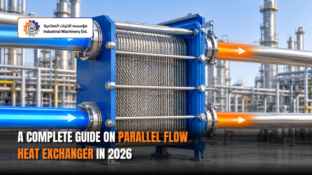
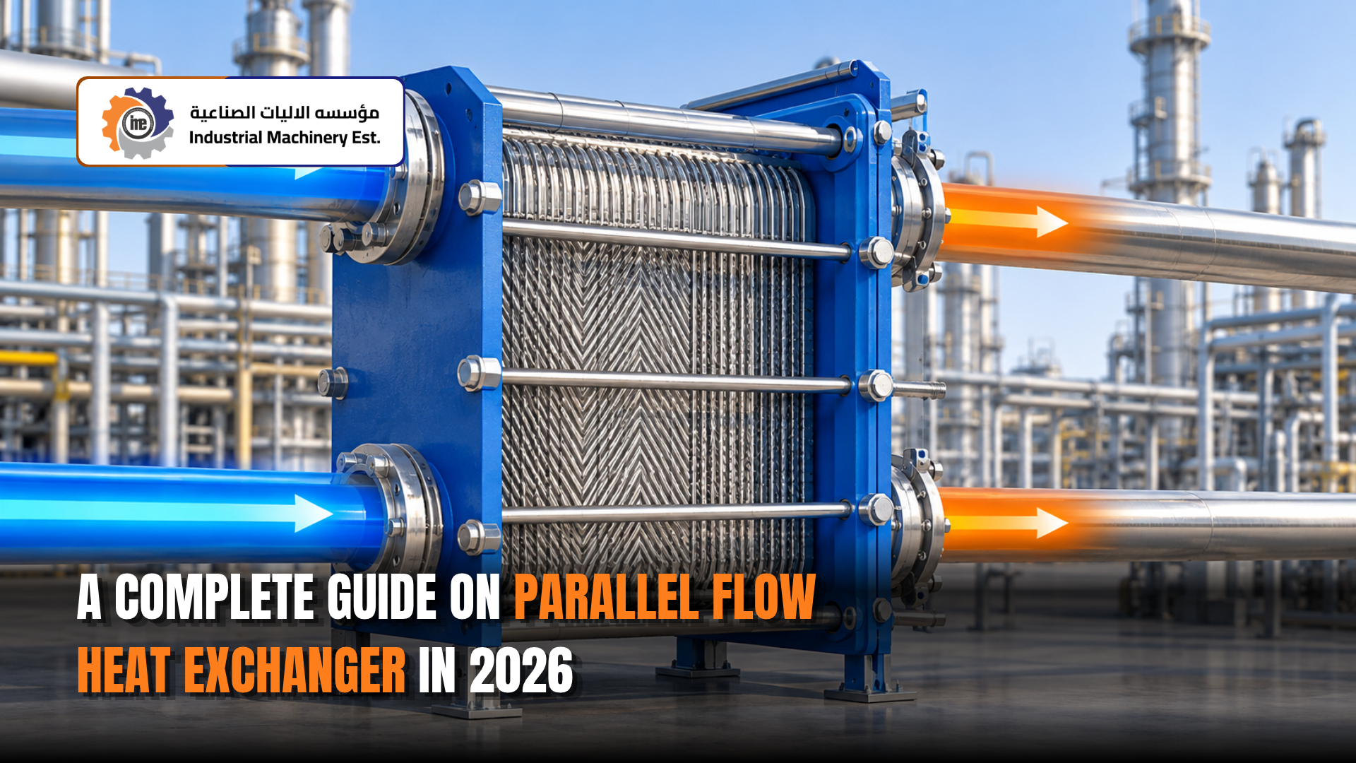
A parallel flow heat exchanger is a device where a hot fluid and a cold fluid enter at the same end, flow in the same direction, and leave at the same end. A solid wall keeps them apart, and heat passes through that wall from the hot fluid to the cold fluid. It is also called a co-current heat exchanger.
Key facts in one place:
- Both fluids move side by side in the same direction
- Heat transfer is fastest at the entry and slows down toward the exit
- The cold fluid can never leave hotter than the hot fluid’s outlet
- It is simple and easy to control, but less efficient than counterflow
How a Parallel Flow Heat Exchanger Works, Step by Step
- Both fluids enter at the same end. The hot fluid enters at its highest temperature, and the cold fluid enters at its lowest temperature.
- They flow side by side. A metal wall, such as a tube or a plate, separates them so they never mix.
- Heat moves through the wall. Heat flows from the hot fluid into the wall, through the metal, and into the cold fluid.
- The temperature gap is biggest at the entry. This is where heat moves fastest.
- The gap shrinks along the length. The hot fluid cools down and the cold fluid warms up, so they get closer in temperature.
- Both fluids exit at the same end. Their outlet temperatures get close to each other, but the cold outlet always stays below the hot outlet.
What Happens to Temperature Inside the Exchanger
If you draw a graph of temperature along the length of a parallel flow exchanger, you see two lines:
- The hot fluid line starts high and drops
- The cold fluid line starts low and rises
- The two lines move toward each other but never cross
This shape explains both the strength and the weakness of parallel flow. The large gap at the start gives quick heating or cooling. The small gap near the end means the last part of the exchanger does very little work.
Main Parts of a Parallel Flow Heat Exchanger
The exact parts depend on the design, but most units have these:
- Shell or outer pipe: Holds one of the fluids on the outside.
- Tubes or inner pipe (tube bundle): Carry the second fluid. Heat passes through the tube walls.
- Tube sheets: Thick plates that hold the tube ends in place and keep the two fluids separate.
- Inlet and outlet nozzles: In parallel flow, both inlets sit at the same end. This is the defining feature.
- Channel head or bonnet: Guides the tube-side fluid into and out of the tubes.
- Baffles: Support the tubes and guide the shell-side fluid.
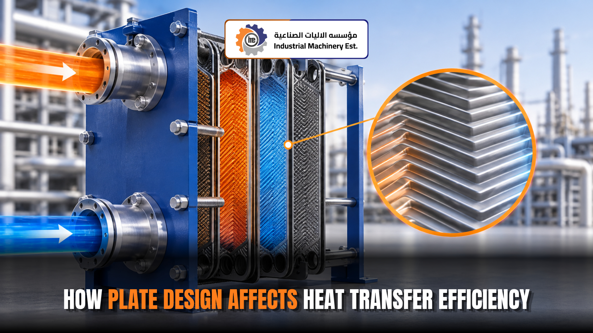
- Plates and gaskets (plate type only): Thin, pressed metal plates with seals between them.
- Expansion joint (in some designs): Absorbs the metal growth caused by large temperature differences.
- Supports or saddles: Hold the unit in place.
Common Designs That Use Parallel Flow
Parallel flow is a flow arrangement, not a single machine. It can be built into several designs:
- Double pipe (tube-in-tube): One pipe inside another. Simple, low cost, and common in labs and small duties.
- Shell and tube: A bundle of tubes inside a large shell. Used for bigger industrial duties.
- Plate heat exchanger: Thin plates stacked together. Compact and easy to clean.
Good to know: Many exchangers can run as parallel flow or counterflow. The difference often comes down to how the pipes are connected at the nozzles.
How to Calculate Heat Transfer in a Parallel Flow Exchanger
Engineers use the Log Mean Temperature Difference (LMTD) method.
Basic formula:
Q = U × A × LMTD
- Q = heat transferred (W)
- U = overall heat transfer coefficient (W/m²·K)
- A = heat transfer area (m²)
- LMTD = log mean temperature difference (°C or K)
LMTD for parallel flow:
LMTD = (ΔT1 − ΔT2) / ln(ΔT1 / ΔT2)
- ΔT1 = hot inlet temperature minus cold inlet temperature
- ΔT2 = hot outlet temperature minus cold outlet temperature
Worked Example
Hot oil enters at 150°C and leaves at 90°C. Water enters at 30°C and leaves at 70°C. The duty is 200 kW and U is 500 W/m²·K.
Parallel flow:
- ΔT1 = 150 − 30 = 120°C
- ΔT2 = 90 − 70 = 20°C
- LMTD = (120 − 20) / ln(6) = 55.8°C
- Area needed = 200,000 / (500 × 55.8) = 7.17 m²
Same job in counterflow:
- ΔT1 = 150 − 70 = 80°C
- ΔT2 = 90 − 30 = 60°C
- LMTD = (80 − 60) / ln(1.33) = 69.5°C
- Area needed = 200,000 / (500 × 69.5) = 5.76 m²
Result: Parallel flow needs about 25% more surface area for the same job. This is the main cost of choosing it.
Effectiveness Limit
Effectiveness tells you how much heat is moved compared to the most that could be moved. For parallel flow:
ε = [1 − exp(−NTU × (1 + Cr))] / (1 + Cr)
When both fluids have equal heat capacity rates (Cr = 1), parallel flow can never go above 50% effectiveness, even with endless surface area. Counterflow has no such limit.
Parallel Flow vs Counterflow vs Cross Flow
| Feature | Parallel Flow | Counterflow | Cross Flow |
| Flow direction | Same direction | Opposite directions | Right angles |
| Temperature gap | Large at entry, small at exit | Fairly even along length | In between |
| Thermal efficiency | Lowest | Highest | Medium |
| Cold outlet hotter than hot outlet? | Never | Possible | Sometimes |
| Area needed for same duty | Largest | Smallest | Medium |
| Best for | Temperature limits, quick cooling, heat-sensitive fluids | Maximum heat recovery | Air and gas cooling, compact units |
Counterflow is the most widely used arrangement. Market Research Future reports that counter-current designs made up 60.5% of installed heat exchanger value in 2025. Parallel flow is used less often, but it wins in specific jobs where its strengths matter.
Advantages of Parallel Flow Heat Exchangers
- Fast heating or cooling at the entry: The large starting temperature gap gives quick results, which is useful when a fluid must be cooled right away.
- Built-in temperature limit: The cold fluid cannot overheat past the hot outlet, which protects heat-sensitive products.
- Lower peak wall temperature: The hottest fluid meets the coldest fluid, so the wall near the hot inlet stays cooler. This helps reduce fouling and coking of sensitive fluids.
- Even, predictable outlet temperatures: Both outlets end up close together, making temperature control easier.
- Simple design: Easy to build, install, and clean.
- No penalty with phase change: When one fluid boils or condenses at a constant temperature, parallel flow performs the same as counterflow.
Limitations to Keep in Mind
- Lower thermal efficiency: Less heat is moved for the same size unit.
- Larger and costlier for the same duty: More surface area means more metal and more space.
- Limited temperature recovery: The cold fluid can never get hotter than the hot fluid’s outlet.
- 50% effectiveness ceiling when both fluids have equal heat capacity rates.
- Weak end section: The exit portion of the exchanger moves very little heat.
- Thermal stress at the entry: The hottest and coldest fluids meet at the same end, which can stress tubes and tube sheets, especially during fast startups.
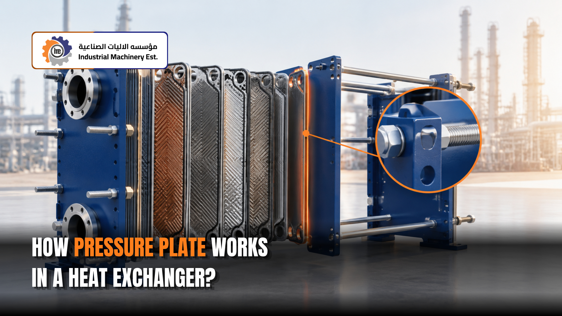
Must Read: How Pressure Plate Works in a Heat Exchanger?
Where Parallel Flow Heat Exchangers Are Used
- Petrochemical and chemical plants: Quick cooling (quenching) of hot process streams to stop unwanted reactions.
- Oil and gas: Fast warming of heavy or viscous oils at the entry to lower their thickness and help them flow.
- Food, dairy, and beverage processing: Heating products that must not go above a set temperature.
- Pharmaceutical production: Gentle heating of temperature-sensitive liquids.
- Power plants and boilers: Duties where one fluid changes phase, so flow direction has no effect on performance.
- Freeze protection: Warming cold fluids quickly at the inlet to stop freezing or wax buildup.
- Engineering education: A standard teaching unit in heat transfer labs because it is simple to build and study.
How Parallel Flow Supports Efficient Industrial Processes
Parallel flow is not the most thermally efficient design, but it can make the whole process more efficient in other ways:
- Protects product quality: Prevents overheating that leads to spoiled batches, rework, or off-spec product.
- Slows fouling: Lower wall temperatures mean fewer deposits on sensitive fluids, so performance holds longer between cleanings.
- Gives fast process response: Quick temperature change at the entry helps control reactions and process conditions.
- Cuts downtime: Simple construction makes inspection and cleaning faster.
- Improves safety: A natural temperature limit lowers the risk of overheating a fluid past safe levels.
When Should You Choose Parallel Flow?
Choose parallel flow when:
- Your product must stay below a set temperature
- You need fast cooling or heating right at the entry
- You want lower wall temperatures to limit fouling or coking
- You need steady, easy-to-control outlet temperatures
- One fluid is boiling or condensing
- The duty is small and you want a simple, low-cost unit
Choose counterflow instead when:
- You want the highest possible heat recovery
- You need the cold fluid to leave hotter than the hot fluid’s outlet
- Space or budget for surface area is tight
Common Problems and How to Fix Them
| Problem | Likely Cause | Fix |
| Outlet temperature misses target | Fouling, low flow rate, or undersized unit | Clean the surfaces, check flow rates, review design or consider counterflow |
| Pressure drop keeps rising | Scale, sludge, or blocked tubes | Chemical or mechanical cleaning |
| Fluids mixing or contamination | Tube leak or gasket failure | Pressure test, plug or replace tubes, replace gaskets |
| Cracks near the inlet tube sheet | Thermal stress from the large entry temperature gap or fast startups | Ramp temperatures up slowly, check expansion joints, inspect welds |
| Corrosion or pitting | Wrong material or poor water quality | Improve water treatment or upgrade material |
| Vibration or noise | Shell-side flow too fast or weak tube support | Check flow rates and baffle condition |
Maintenance Tips to Keep Performance High
- Log temperatures: Record inlet and outlet temperatures on both sides and compare them to design values.
- Track pressure drop: A steady rise is an early warning of fouling.
- Watch the U value over time: A falling U value shows how fast deposits are building up.
- Clean before performance drops too far: Plan cleaning during scheduled shutdowns.
- Treat cooling water: Good water chemistry reduces scale and corrosion.
- Inspect the inlet end closely: This zone sees the most thermal stress.
- Start up and shut down slowly: Gradual temperature changes protect tubes and tube sheets.
What Is Changing for Heat Exchangers in 2026
- Live monitoring: More plants are adding temperature and pressure sensors to spot fouling early instead of waiting for a failure.
- Predictive maintenance: Performance data is being used to plan cleaning based on real condition, not fixed dates.
- Stronger focus on waste heat recovery: Rising energy costs are pushing plants to recover more heat, which is shaping how flow arrangements are chosen.
- Better materials and coatings: New surface treatments help resist fouling and corrosion.
- Flexible plate designs: Compact plate units that can be piped for either parallel or counterflow give plants more options.